HTB Academy OSI-Model and Protocol breakdown
HTB Academy OSI-Model and Protocol breakdown: Networking Primer - Layers 1-4 The image below gives a great view of the Open Systems Interconnect (OSI) model and the Transmission Control Protocol - Internet Protocol (TCP-IP) model side by side. The models are a graphical representation of how communication is handled between networked computers. Let's take a second... • HTB Academy • htb-academy, module81
Networking Primer: Layers 1–4
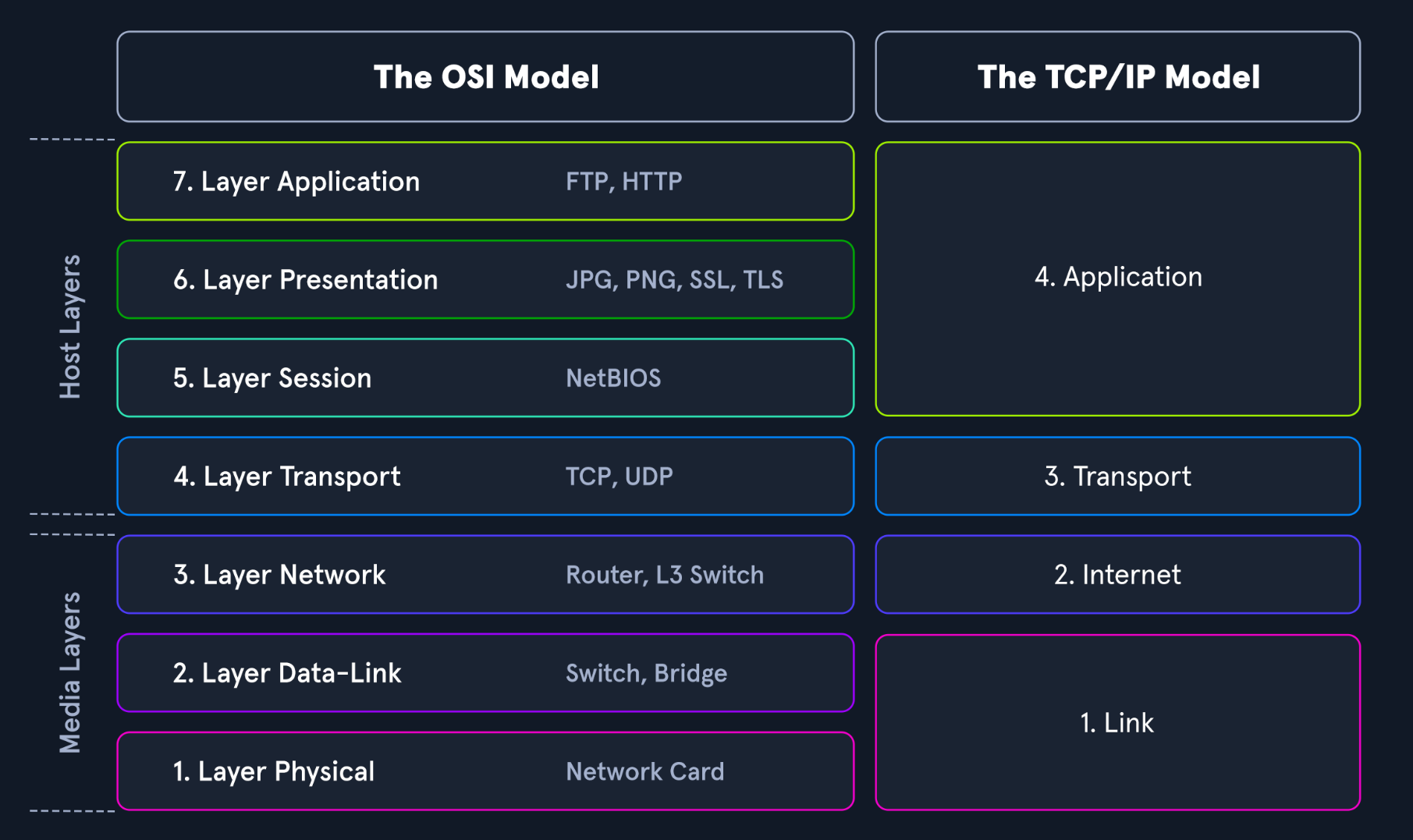
The image below provides an overview of the Open Systems Interconnection (OSI) model and the Transmission Control Protocol/Internet Protocol (TCP/IP) model side by side.
These models are graphical representations of how communication is handled between networked computers.
Protocol Data Units
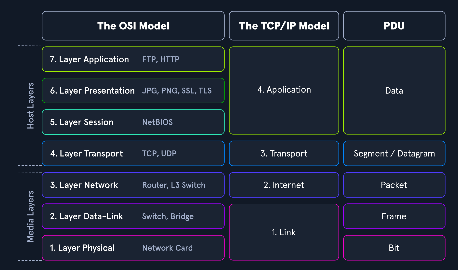
Throughout this module, we will examine different Protocol Data Units (PDUs). A functional understanding of how they appear in theory and on the wire is therefore required.
A PDU is a data packet made up of control information and data encapsulated at each layer of the OSI model.
The following comparison shows how the layers in the two models relate to each other.
Model Traits Comparison
| Trait | OSI | TCP/IP |
|---|---|---|
| Layers | Seven | Four |
| Flexibility | Strict | Loose |
| Dependency | Protocol-independent and generic | Based on common communication protocols |
Encapsulation
When inspecting a PDU, we must keep the concept of encapsulation in mind.
As data moves down the protocol stack, each layer wraps the previous layer's data with additional information. This process is called encapsulation.
Each layer adds its own header information to the PDU. Depending on the layer, this information may include:
- Data from the previous layer
- Operational flags
- Communication options
- Source and destination IP addresses
- Source and destination ports
- Transport protocols
- Application-layer protocols
PDU Packet Breakdown
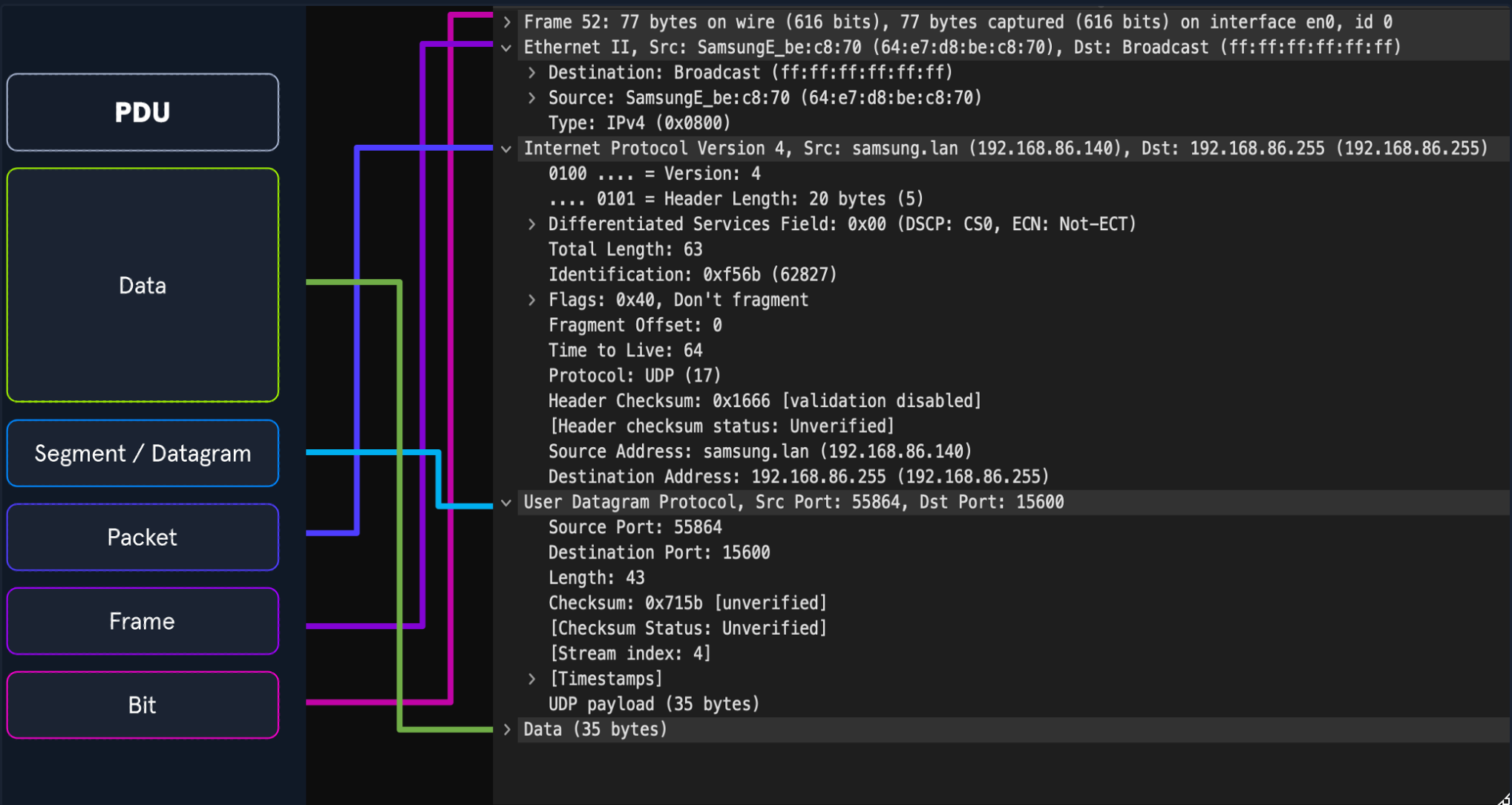
The image above shows the structure of a PDU next to a packet breakdown from Wireshark's Packet Details pane.
Wireshark displays the PDU in reverse order because it shows the order in which the data was unencapsulated.
Addressing Mechanisms
Now that we have reviewed the basic concepts behind networking behavior, we can examine the addressing mechanisms that allow packets to reach the correct hosts.
We will begin with Media Access Control addresses.
MAC Addressing
Each logical or physical interface attached to a host has a Media Access Control (MAC) address.
A MAC address is a 48-bit address consisting of six octets represented in hexadecimal format.
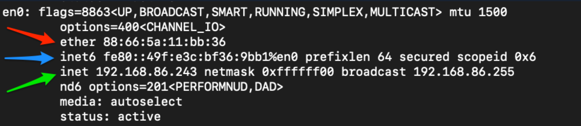
The image below shows an example of a MAC address indicated by the red arrow.
MAC addressing is used for Layer 2 communication.
Depending on the networking model, Layer 2 is called:
- The Data Link layer in the OSI model
- The Link layer in the TCP/IP model
MAC addressing enables host-to-host communication within a broadcast domain.
When Layer 2 traffic must cross a Layer 3 interface, the PDU is sent to the router's egress interface and routed toward the correct network.
At Layer 2, the PDU appears to be addressed to the router interface. The router then examines the Layer 3 address to determine where the packet should be sent next. It removes the existing Layer 2 encapsulation and replaces it with new Layer 2 information for the next physical destination.
IP Addressing
The Internet Protocol (
IP) was developed to deliver data from one host to another across network boundaries.
IP is responsible for:
- Routing packets
- Encapsulating data
- Fragmenting datagrams
- Reassembling datagrams at the destination
IP is a connectionless protocol. It does not guarantee that data will reach its intended recipient.
For reliable and validated data delivery, IP relies on upper-layer protocols such as TCP.
There are currently two main versions of IP:
- IPv4
- IPv6
IPv4
Internet Protocol version 4 (IPv4) is the addressing mechanism most users are familiar with.
IPv4 is the primary method used to route packets across networks to hosts outside the local network.
The image below shows an IPv4 address indicated by the green arrow.
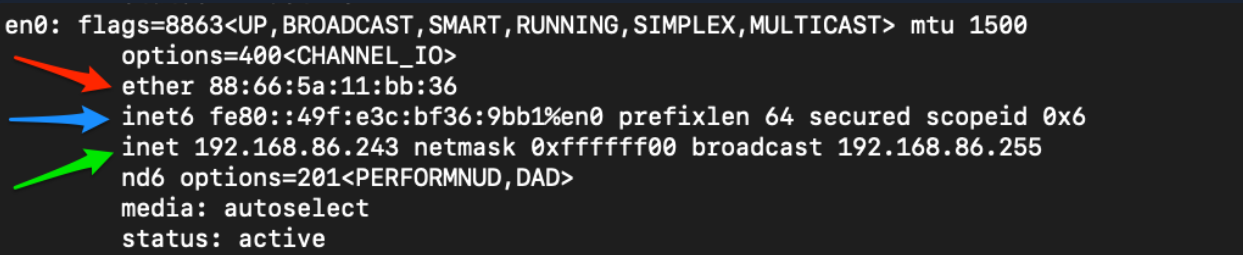
An IPv4 address is a 32-bit address consisting of four octets represented in decimal format.
Example:
192.168.86.243Each octet can contain a value from 0 to 255.
When examining a PDU, IPv4 addresses are located at:
- Layer 3, the Network layer, in the OSI model
- Layer 2, the Internet layer, in the TCP/IP model
IPv6
After IPv4 had been used for some time, it became clear that the available pool of IPv4 addresses would eventually be exhausted.
Large sections of the IPv4 address space were reserved for private addressing and other special purposes.
Two major solutions were introduced:
- Variable Length Subnet Masks (
VLSM) and Classless Inter-Domain Routing (CIDR) - Internet Protocol version 6 (
IPv6)
VLSM and CIDR improved how IPv4 addresses could be allocated.
IPv6 was created as the long-term successor to IPv4.
IPv6 provides a significantly larger address space.
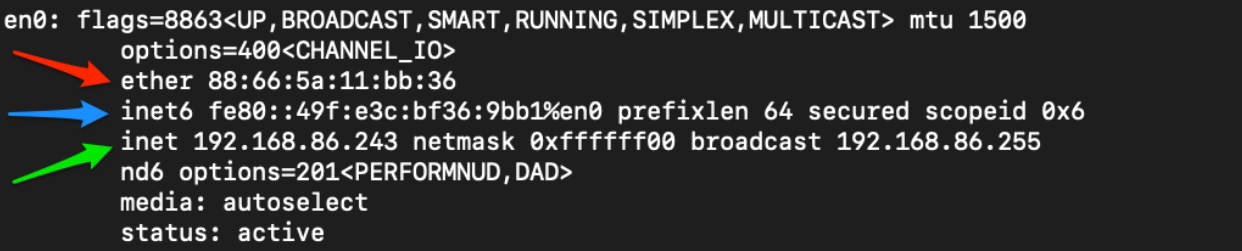
An IPv6 address is:
- 128 bits long
- Made up of 16 octets
- Represented in hexadecimal format
The image below shows a shortened IPv6 address indicated by the blue arrow.
IPv6 also provides:
- Better multicast support
- Global addressing for individual devices
- Built-in support for IPsec
- Simplified packet headers
- Easier packet processing
- The ability to move between connections without necessarily being assigned a new address
IPv6 Address Types
| Type | Description |
|---|---|
Unicast | Identifies a single interface. |
Anycast | Identifies multiple interfaces, but only one receives the packet. |
Multicast | Identifies multiple interfaces, and all of them receive the packet. |
Broadcast | Does not exist in IPv6 and is instead implemented using multicast. |
A useful way to remember these address types is:
- Unicast: one host to one host
- Multicast: one host to many hosts
- Anycast: one host to a group, where only one member responds
Anycast is commonly associated with load balancing.
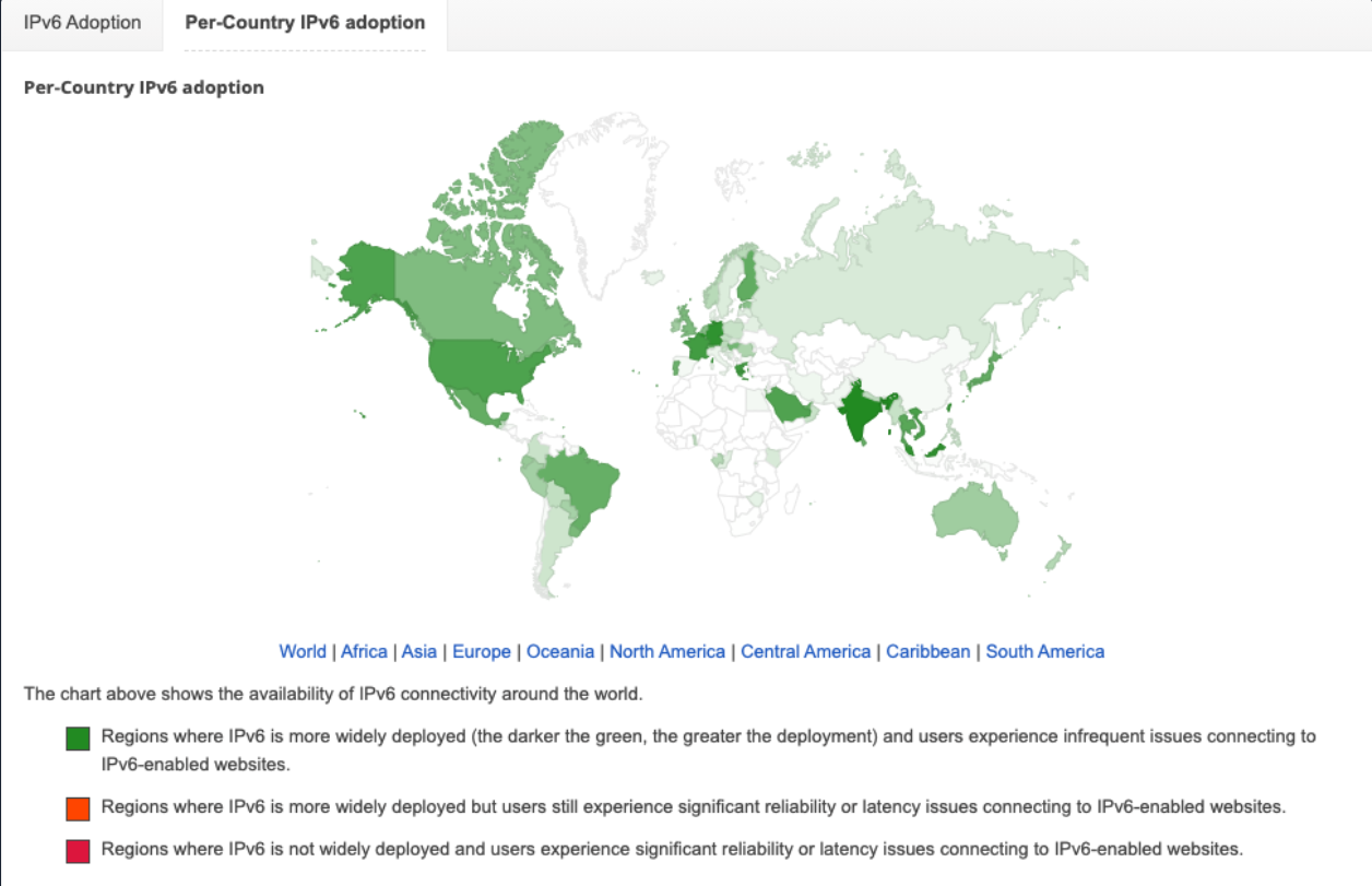
Despite the advantages of IPv6, its adoption has historically been slower than expected.
TCP and UDP Transport Mechanisms
The Transport layer contains several mechanisms that help deliver data from a source to a destination.
The Transport layer can be thought of as a control hub.
Application data from the higher layers moves down the protocol stack until it reaches the Transport layer.
The Transport layer determines how traffic is encapsulated and passed to lower-layer protocols such as IP and Ethernet.
When the data reaches the destination, the Transport layer works with the Network or Internet layer to reassemble the encapsulated data in the correct order.
The two main transport protocols are:
- Transmission Control Protocol (
TCP) - User Datagram Protocol (
UDP)
TCP vs. UDP
| Characteristic | TCP | UDP |
|---|---|---|
| Transmission | Connection-oriented | Connectionless |
| Connection establishment | Uses a three-way handshake | Does not establish a connection |
| Data delivery | Stream-based and ordered | Packet-based and independent |
| Receipt confirmation | Uses sequence and acknowledgment numbers | Does not acknowledge delivery |
| Reliability | Reliable | Unreliable |
| Speed | Slower due to additional overhead | Faster due to lower overhead |
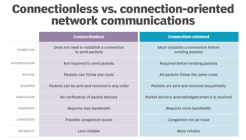
TCP and UDP provide very different methods of transmitting data.
TCP is considered more reliable because error checking and acknowledgment are built into the protocol.
UDP is a fast, connectionless protocol that is useful when speed is more important than guaranteed delivery.
TCP Example
TCP is used when completeness and reliability are more important than speed.
For example, Secure Shell (SSH) uses TCP when connecting from one host to another.
An SSH connection remains active while commands are issued and actions are performed.
TCP helps ensure that communication with the remote host is not interrupted or delivered incorrectly.
If part of a message is lost, TCP does not pass an incomplete command to the application.
Consider the following command:
sudo passwd userIf part of this command were lost during transmission, it could lead to unexpected results.
TCP avoids this problem by acknowledging packets and ensuring that the destination receives the complete data before passing it to the application.
UDP Example
UDP is useful when fast responses are more important than complete delivery.
Video streaming is one example.
A user may not notice if a small number of pixels or packets are lost. It is often more important that the video continues playing without repeatedly stopping to buffer.
DNS is another example.
When a host requests a DNS record, it generally expects a quick response. If the request or response is lost, the request can simply be sent again.
UDP traffic usually consists of individual packets without acknowledgments or confirmation that the packet was received.
TCP Three-Way Handshake
TCP uses sessions to help ensure reliable data delivery between clients and servers.
These sessions are established using a process called the three-way handshake.
TCP uses flags in the TCP header during this process.
The primary flags used during the handshake are:
- Synchronization (
SYN) - Acknowledgment (
ACK)
The handshake consists of three steps.
Step 1: Client Sends SYN
The client sends a TCP packet with the SYN flag set.
This packet begins sequence-number synchronization between the client and server.
During this stage, the client and server may also negotiate options such as:
- Window size
- Maximum Segment Size (
MSS) - Selective Acknowledgments (
SACK) - Initial sequence numbers
Step 2: Server Sends SYN-ACK
The server responds with a packet containing both the SYN and ACK flags.
The ACK acknowledges the client's original synchronization request.
The server also sends its own synchronization information and may include changes to the negotiated TCP options.
Step 3: Client Sends ACK
The client responds with a packet containing the ACK flag.
This packet acknowledges the server's synchronization information and completes the connection establishment.
The final sequence is:
Client → Server: SYN
Server → Client: SYN, ACK
Client → Server: ACK
TCP Three-Way Handshake Example
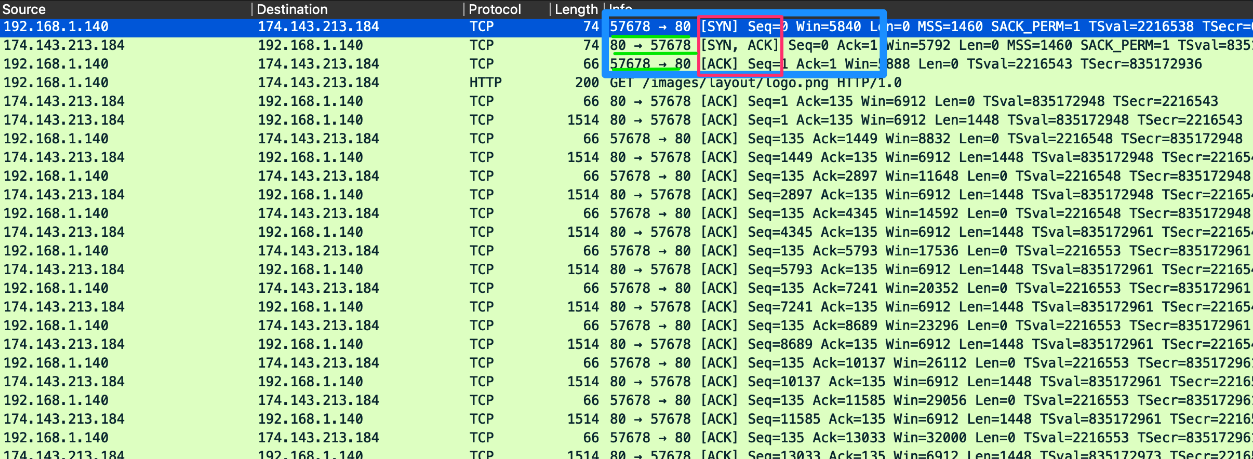
In the packet capture:
- The client sends a packet with the
SYNflag. - The server responds with
SYN, ACK. - The client responds with
ACK. - The HTTP request is sent after the connection has been established.
The port numbers shown include:
57678: A temporary high-numbered client port80: The well-known server port for HTTP
As the data stream continues, TCP sends acknowledgments for the transmitted data.
TCP Session Teardown
TCP connections can be closed gracefully using the FIN flag.
The FIN flag indicates that the sender has finished transmitting data and wants to terminate the connection.
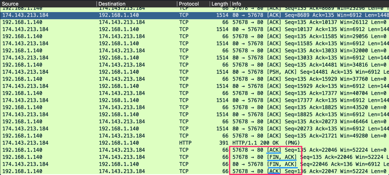
During session termination:
- One side sends a
FINpacket. - The other side acknowledges the
FIN. - The other side sends its own
FIN. - The original sender acknowledges the final
FIN.
A simplified packet pattern may appear as:
FIN, ACK
FIN, ACK
ACK
This pattern indicates that the TCP connection was terminated gracefully.
Comments
Comments
Loading comments…